F5 DNS Labs
Lab Access
Log in to the Ravello training portal at https://ravello.example.com
Find the IP address for the Windows jumpbox found in the in the Ravello training portal.
All lab excercises are to be completed from the Windows “jumpbox”.
**TODO Update the screenshot with annotations
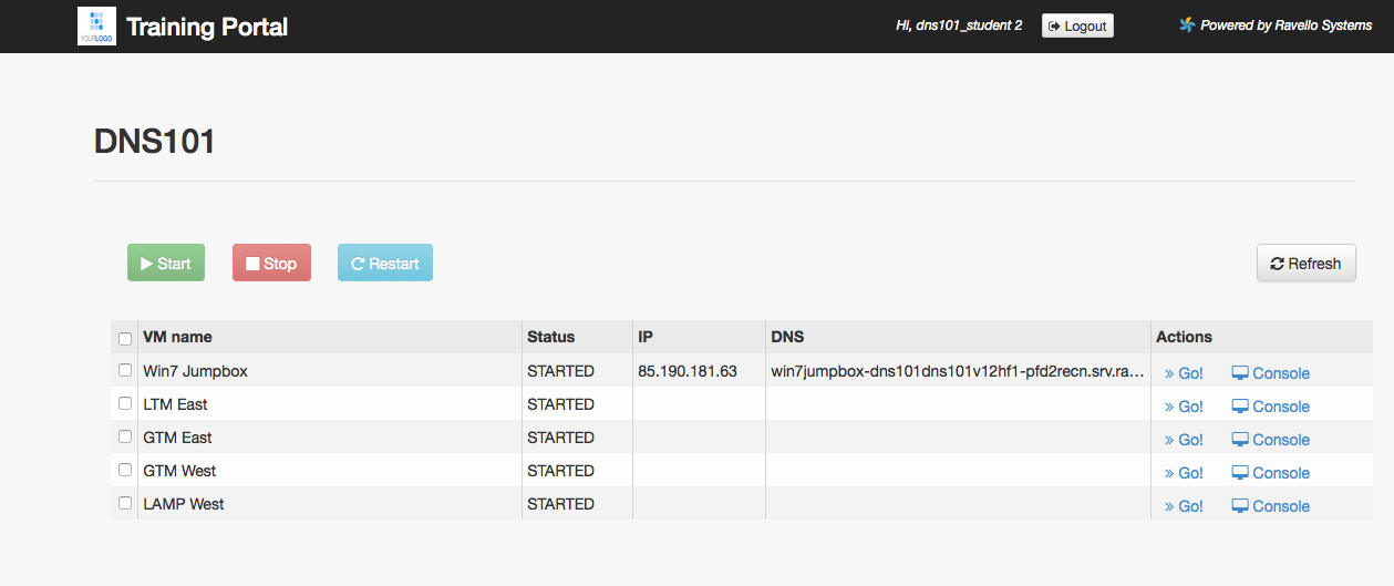
NOTE: All of the VMs should be in a STARTED state.
Username: user
Password: Agility1
Network Topology
The lab consists of two datacenters and a branch office. A Microsoft Active Directory Domain “EXAMPLE” runs in the branch office along with a Windows-7 “jumpbox” for remote desktop. Each “site” or “datacenter” consists of one standalone GTM, an HA pair of fully licensed BIG-IP’s, as well as distributed application servers running containers of Apache,MySQL,PHP.
TODO - Insert Visio diagram here
The lab environment is pre-configured with basic system and networking settings.
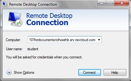
Use Internet Explorer Browser on the jumpbox to log in via the GUI, or use Putty for SSH to get a shell.
GUI username = admin/admin
CLI username = root/default
Management IP Addresses:
| Site 1 | Site 2 |
|---|---|
| bigip1.site1 = 10.1.10.11 | bigip1.site2 = 10.1.10.21 |
| bigip2.site1 = 10.1.10.12 | bigip2.site2 = 10.1.10.22 |
| gtm1.site1 = 10.1.10.13 | gtm1.site2 = 10.1.10.23 |
Service IP Addresses:
| Site 1 | Site 2 |
|---|---|
| www.example.com = 203.0.113.9 | www.example.com = 198.51.100.41 |
| vpn.example.com = 203.0.113.10 | vpn.example.com = 198.51.100.42 |
GSLB
Initial Setup
- Objective: To start off the labs, you will run through some basic
configuration steps to get GTM1.SITE1 (10.1.10.13) up and
operational. Networking and NTP are already configured. You will be
configuring the following:
- DNS Logging
- DNS Profile and Listeners
- Data Centers
- Server Objects
- Local LTM Virtual Server
- Estimated completion time: 25 minutes
Logging
- Configure DNS query and response logging. To do > this, you must tell GTM where to send logs to (a log publisher) > and what specifically to log (DNS logging profile).
- For lab purposes, we are going to use local-syslog as our > logging destination. Note that remote high speed logging is the > recommendation for production environments.
- In the GUI, navigate to: System > Logs > Configuration > > Log Publishers: Create
- Create a new DNS Log Publisher as shown in the table below. Keep the > defaults if not noted in the table.
| Name | dns-local-syslog |
|---|---|
| Destinations | Move dns-local-syslog to the Selected column |
| Click Finished |
- In the GUI, navigate to: DNS > Delivery > Profiles > > Other > DNS Logging: Create
- Create a new DNS logging profile as shown in the table below. Keep > the defaults if not noted in the table.
| Name | dns-logging |
|---|---|
| Log Publisher | Select dns-local-syslog |
| Log Responses | Enabled |
| Include Query ID | Enabled |
| Click Finished |
- Your new dns-logging profile should now have all options enabled.
DNS Profile
- A DNS profile tells the DNS Listener how to process DNS traffic. > We’re going to make some basic tweaks.
- In the GUI, navigate to: DNS > Delivery > Profiles > DNS: > Create
- Create a new DNS profile as shown in the following table. Keep the > defaults if not noted in the table.
| Name | my_dns |
|---|---|
| Unhandled Query Action | Drop |
| Use BIND Server on Big-IP | Disabled |
| Logging | Enabled |
| Logging Profile | dns-logging |
| Click Finished |
Listeners
Create UDP/TCP external Listeners. You will use this IP as a target address when querying GTM.
In the GUI, navigate to: DNS > Delivery > Listeners > Listener List: Create
- Create two external Listeners as shown in the tables below. Keep the > defaults if not noted in the table.
| Name | Listener-UDP |
|---|---|
| Destination | Host: 10.128.10.245 |
| VLAN Traffic | Enabled on.. |
| VLANs and Tunnels | External |
| DNS Profile | my_dns |
| Click Finished |
| Name | Listener-TCP |
|---|---|
| Destination | Host: 10.128.10.245 |
| VLAN Traffic | Enabled on.. |
| VLANs and Tunnels | external |
| **Protocol ** | TCP |
| DNS Profile | my_dns |
| Click Finished |
Data Centers
- In the GUI, navigate to: DNS > GSLB > Data Centers > Data > Center List: Create
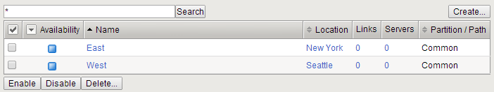
- Create two Data Centers as shown below. Leave all defaults unless > otherwise noted:
| Name | East |
|---|---|
| Location | New York |
| Click Finished |
| Name | West |
|---|---|
| Location | Seattle |
| Click Finished |
Your Data Center list should look like the diagram below. Why is the > status blue?
Servers
By default, GTM is not self-aware. You will need to configure your BigIP as a server object.
- In the GUI, navigate to: DNS > GSLB > Servers > Server > List: Create
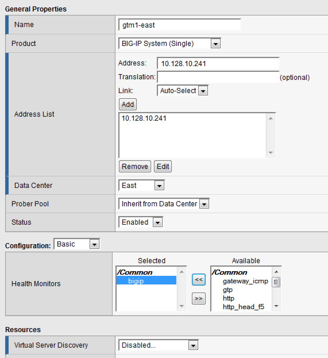
- Create a Server Object as defined in the table and diagram below. > Leave default values unless otherwise noted:
| Name | gtm1-east |
|---|---|
| Product | Big-IP (Single) |
| Address List | 10.128.10.241 (Add) |
| Data Center | East |
| Health Monitors | Bigip |
| Virtual Server Discovery | Disabled |
| Click Create |
Click on the “Server List” tab at the top menu bar to refresh the page. You should see the Server object as green.
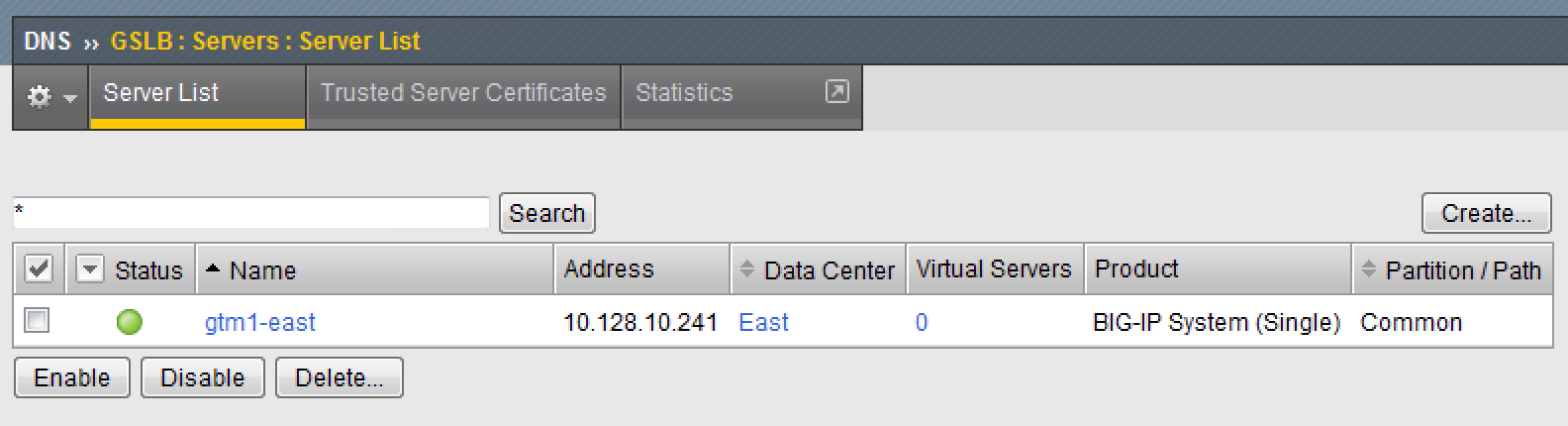 What is the status of the East Data Center object now?
LTM HA Pairs
Students will be using an LTM object to serve as the East-LTM. You will need to create another BigIP object to do this. Prior to configuring the Server object, we need to establish trust between the GTM and LTM. The bigip_add script will exchange device certificates to establish a trust relationship.
Login via SSH using putty to your GTM1 (10.128.1.245) using username: root password: agility
- Issue the following commands.bigip_add 10.128.1.245
Type ‘yes’ to proceed and enter ‘agility’ as the password.
Now type:big3d_install 10.128.1.245Note that this script likely won’t need to install a new version of the big3d agent… this is just for you to be familiar with the script.
From the GTM1 GUI, navigate to: DNS > GSLB > Servers> > Server List: Create
Create a Server Object as defined in the table and diagram below. > Leave default values unless otherwise noted:
| Name | ltm-east |
|---|---|
| Product | Big-IP (Single) |
| Address List | 10.128.10.240 (Add) |
| Data Center | East |
| Health Monitors | Bigip |
| Virtual Server Discovery | Enabled |
| Click Create |
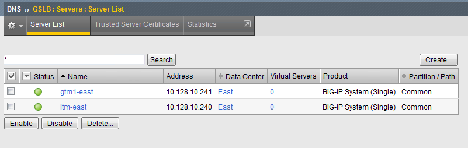
After a few moments, click on the “Server List” tab at the top menu > bar to refresh the page. You should see the Server object > as green. You should also see virtual servers auto-discovered. > Below is a sample of what your screen should look like:
- Go to your SSH session on GTM1 and take a look at the /var/log/gtm > file to see what kinds of logs are generated after a server is > created.>> **tail -100 /var/log/gtm > **
Generic Host
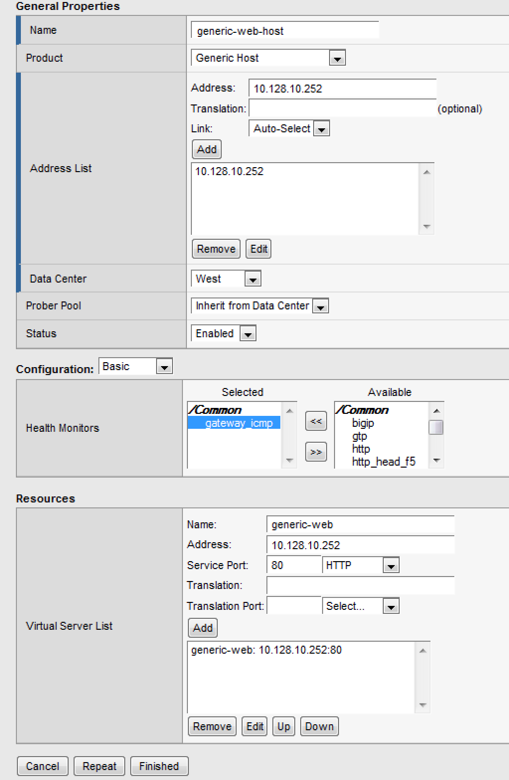
GTM can handle virtual servers that do not reside on a BigIP. The most common way of incorporating non-F5 virtual server is using a Server type of Generic Host.
In the GUI, navigate to: DNS > GSLB > Servers > Server > List: Create
Create a Server Object as defined in the diagram below. Note that > the web virtual server is manually configured here and happens to > be the same IP address as the physical host.
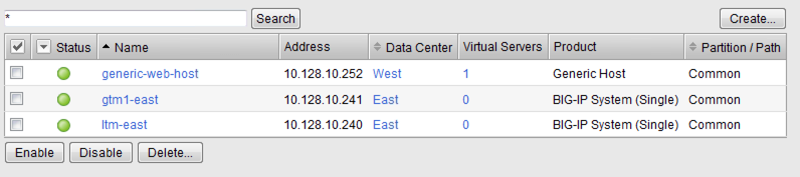
After a few moments, click on the “Server List” tab at the top menu bar to refresh the page. You should eventually see the Server object as green.
Virtual Servers
Finally, we need to create another virtual server on our LTM–East (10.128.1.245)
- Login to https://10.128.1.245 with admin\agility if you haven’t > already
- In the GUI, navigate to: Local Traffic > Pools > Pool List: > Create
- Create a LTM Pool as defined in the table below. Leave default > values unless otherwise noted:
| Name | pool_webapp1_east |
|---|---|
| Health Monitors | http |
| New Members | Address: 10.128.20.11 |
| Service Port: 80 Address: 10.128.20.12 | |
| Service Port: 80 | |
| Click Finished |
- In the GUI, navigate to: Local Traffic > Virtual Servers > > Virtual Server List: Create
- Create a Virtual Server as defined in the table and diagram below. > Leave default values unless otherwise noted:
| Name | virtual_webapp1_east |
|---|---|
| Destination (Host) | 10.128.10.10 |
| Service Port | 80 |
| Source Address Translation | Auto Map |
| Default Pool | pool_webapp1_east |
**Test new east coast virtual server in browser by hitting : http://10.128.10.110
Return to GTM1 GUI and navigate to: DNS > GSLB > > Servers > Server List. You should now see that the > gtm1-east has auto-discovered 1 new Virtual Server for the > ltm-east server for a total of 2 Virtual Servers.
In the GUI, navigate to: Statistics > Module Statistics > > DNS > GSLB. Select “iQuery” from the Statistics > Type menu.
Active/Standby Data Centers
- In this use-case, you will configure a WideIP for a disaster recovery scenario. In this case, East will always be preferred while West is only used if East is down.
- Estimated completion time: 10 minutes
GTM Pool
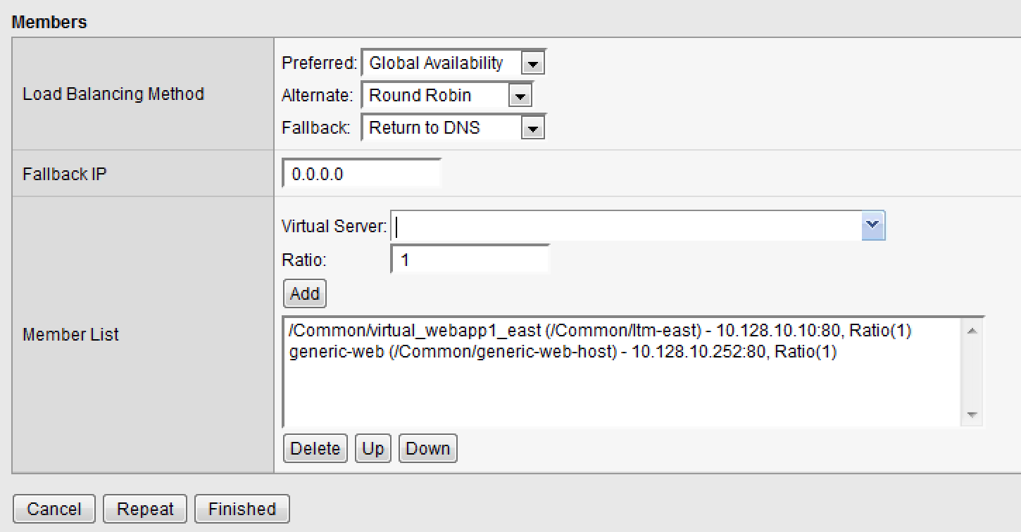
- From the GTM1 GUI, navigate to: DNS > GSLB > Pools > Pool > List: Create. Create a new Pool as shown in the table and > diagram below. Keep the defaults if not noted in the table.
| Name | pool_DR |
|---|---|
| Type | A |
| Load Balancing Method | Preferred: Global Availability |
| Virtual Servers | Virtual_webapp1_east – 10.128.10.10 |
| Generic_host_west – 10.128.10.252 |
Make sure that the east VS is at the top of the Member List as shown below. This is an ordered failover from top to bottom.
WideIP
We will create a hostname to use as a Wide IP.
- In the GUI, navigate to: DNS > GSLB > Wide IPs > Wide IP > List: Create. Create a new Wide IP as shown in the table below. > Keep the defaults if not noted in the table.
| Name | dr.webapp1.com |
|---|---|
| Type | A |
| Pools – Pool List | pool_DR (Add) |
Open a Command Prompt window on your Windows jump box and query your > Listener for the Wide IP. You may wish to issue this command > several times:
nslookup.dr.webapp1.com 10.128.10.245
Your results should look like the following example:
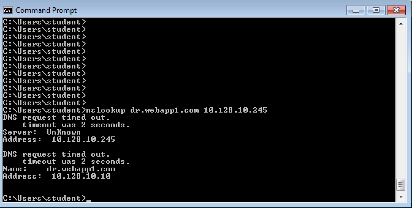
Try hitting **http://dr.webapp1.com** in a browser. You should get the East Coast Data Center every time.
Now is a good time to view query logging. In the SSH shell on the GTM, view the logs in /var/log/ltm:**tail –f /var/log/ltm **
- Now we are going to intentionally fail the east VS. To do this, we’re going to assign a bad monitor to the LTM VS to simulate the application failing. Before we do this, open an SSH session to your GTM1 and tail the log file: tail –f /var/log/gtm
While the log is updating, navigate in the LTM-East to Local Traffic > Pools > Pool List. Select the pool_webapp1_east pool. Change the selected Health Monitor to udp as shown below:
 The LTM pool will turn red in about 30 seconds and you will see log messages in /var/log/gtm show up showing that GTM has learned the health via iQuery.Query the WideIP again from the Command Prompt and note the results. The west server IP should be returned.nslookup.dr.webapp1.com 10.128.10.245
10.128.10.252 <- Generic Host in the West Data Center
You can also try refreshing the web page from a browser – you should be directed to the Node #3 (green headline)
Now go back and remove the https monitor on virtual-server-east-pool and put back the http monitor. Note the log messages in /var/log/gtm.
Query the WideIP again and note your results. Did it fail back?
Fallback
We will create a scenario for a fallback option when both east and west Virtual Servers are unavailable.
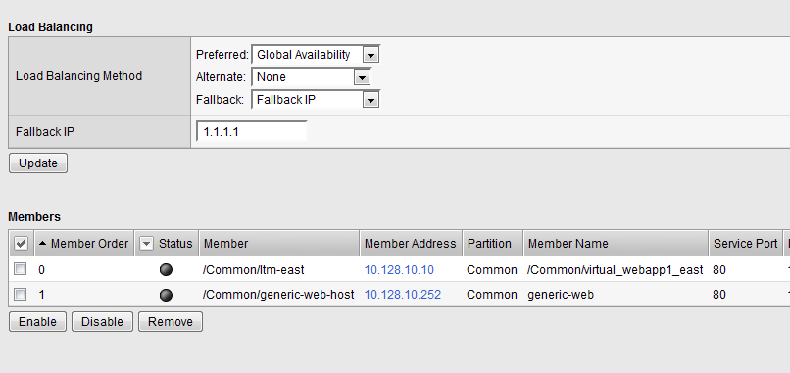
- In the GTM1 GUI, navigate to : DNS > GSLB > Pools > Pool List. Select the pool pool_DR. Select the Members tab in the middle menu bar. Make the following changes as noted in the table.
| **Load Balancing Method ** Preferred: Global Availability Alternate: None |
| Fallback: Fallback IP |
**Fallback IPv4 ** 1.1.1.1
Click Update
Now highlight both members in the checkboxes to the left and click Disable. Your GUI should look similar to the following diagram:
- In the Command Prompt window, query the WideIP again and note the results. They should look similar to below and show fallback:nslookup.dr.webapp1.com 10.128.10.245
- Fallback IP address which can be a sorry server for maintenance
Return to the GTM1 GUI go to Statistics > Module Statistics > DNS > GSLB. Under ‘Statistics Type’, select Pools. You should see statistics for Preferred, Alternate, and Fallback algorithms. You should see Fallback statistics updated:
Go back and re-enable your pool members.
GSLB Active/Active Data Centers
- In this use-case, you will configure a WideIP that sends clients to both East and West Data Centers. This will involve scenarios with and without persistence.
- Estimated completion time: 15 minutes
GTM Pool
- In the GUI on your GTM, navigate to: DNS > GSLB > Pools > > Pool List: Create. Create a new Pool as shown in the table and > diagram below. Keep the defaults if not noted in the table.
| Name | pool_RR |
|---|---|
| Type | A |
| Load Balancing Method | Preferred: Round Robin (default) |
| Add Virtual Servers | Virtual_webapp1_east – 10.128.10.10 |
| generic_web – 10.128.10.252 | |
| Click Finished |
WideIP
We will create a hostname to use as a Wide IP.
- In the GUI, navigate to: DNS > GSLB > Wide IPs > Wide IP > List: Create. Create a new Wide IP as shown in the table below. > Keep the defaults if not noted in the table.
| Name | rr.webapp1.com |
|---|---|
| Type | A |
| Pools – Pool List | pool_RR (Add) |
| Click Finished |
From Command Prompt on your Windows machine, query your Listener for > the Wide IP. You may wish to issue this command several times:
nslookup.rr.webapp1.com 10.128.10.245
You should see the east and west coast IPs returned in a round robin fashion - sometimes 2 in a row for each due to the multiple instances of TMM running on the virtual appliance.
You can also see the results in a browser by going to **http://rr.webapp1.com**
Refresh the page several times and you should see the round robin behavior in the browser.
Your results should have round robin of answers going between east and west Virtual Servers.
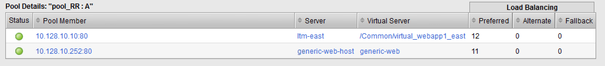
- From GTM1 GUI to Statistics > Module Statistics > DNS > GSLB. Under ‘Statistics Type’, select Pools. Click on View under the ‘Members’ column for pool_RR. You should see an even distribution between members similar to the diagram below:
WideIP Alias
GTM allows for a single WideIP configuration to be used for multiple names, including wildcards. We are going to add a domain name and an example wildcard.
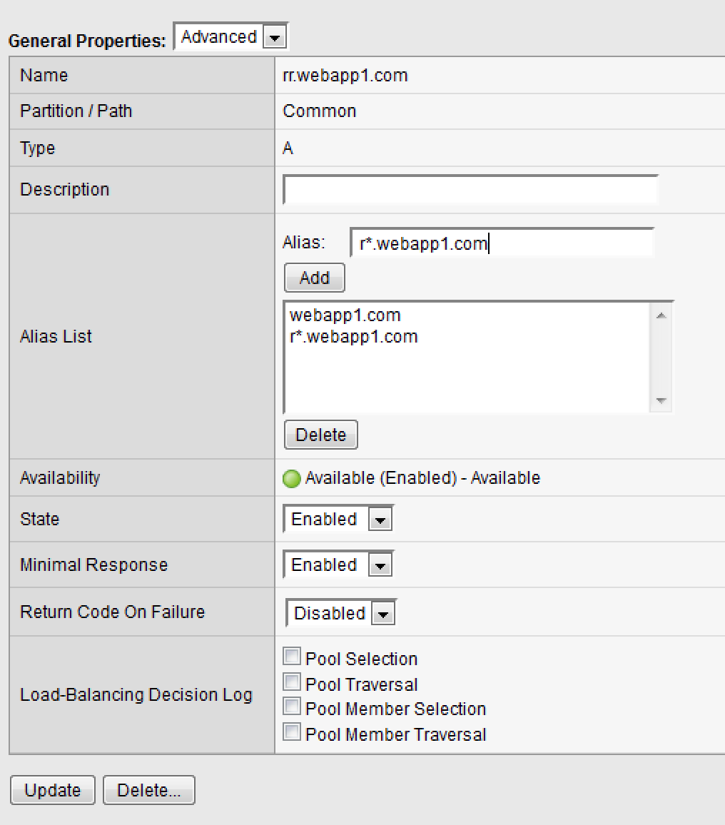
In the GUI, navigate to: DNS > GSLB > Wide IPs > Wide IP List. Select *rr.webapp1.com* and change General Properties to Advanced. Under the Alias List, add the following entries as shown in the diagram below.
webapp1.com
r*.webapp1.com
Issue each of the following DNS queries multiple times from a Command Prompt:
nslookup.webapp1.com 10.128.10.245
nslookup.rooster.webapp1.com 10.128.10.245
Do you see a round robin behavior with above names as expected?
Persistence
Many applications require session persistence. As a result, GTM needs to send clients to the same Data Center via GSLB-level persistence.
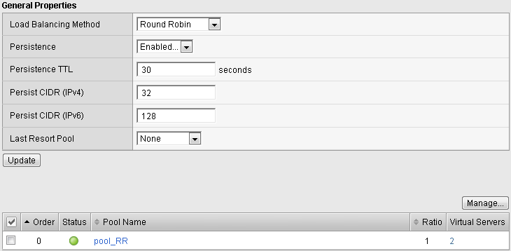
From the GTM1 GUI, navigate to: DNS > GSLB > Wide IPs > Wide IP List. Select *rr.webapp1.com*. Select Pools from the middle menu bar. Make the following changes
Enable Persistence
Change the Persistence TTL to 30 seconds
From Command Prompt, query the WideIP *rr.webapp1.com* several times and note the results. Do you see the same response each time?
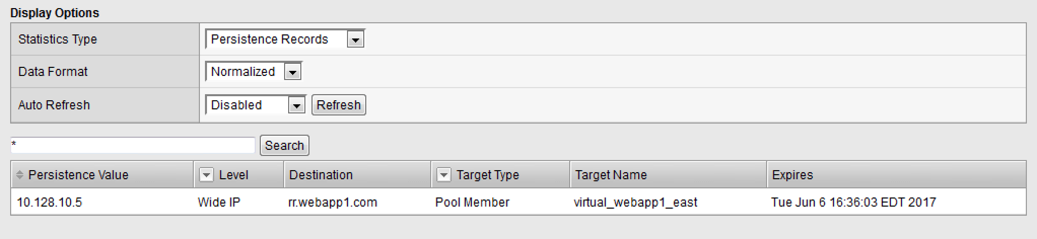
In the GUI, navigate to: Statistics > Module Statistics > DNS > GSLB. Under ‘Statistics Type’, select Persistence Records. Note that because the Persistence TTL is only 30 seconds, you may need to send another query to generate a record. After 30 seconds expires, you should note the record disappearing.
**NOTE: As of v12, persistence record statistics and logging is disabled. If you get the error message in the GUI, follow the directions and run the following from the CLI on GTM1. This will change the DB variable to allow you to view the persistence records in the GUI:
tmsh
modify sys db ui.statistics.modulestatistics.dnsgslb.persistencerecords value true
- Query the Wide IP again and then refresh the persistence record screen in the GUI
Topology
- In this use-case, you will send clients to a preferred geographic location using Topology. We are also going to incorporate the use of multiple pools in this lab to introduce WideIP-level load balancing.
- Estimated completion time: 10 minutes
GTM Pools
- From the GTM1 GUI, navigate to: DNS > GSLB > Pools > Pool > List: Create. Create new Pools as shown in the table and > diagram below. Keep the defaults if not noted in the table.
| Name | pool-east |
|---|---|
| Type | A |
| Load Balancing Method | Preferred: Global Availability |
| Add Virtual Servers | Virtual_webapp1_east - 10.128.10.10:80 |
| generic_web – 10.128.10.252:80 (add this in case the east server becomes unavailable) | |
| Click Finished |
| Name | pool-west |
|---|---|
| Type | A |
| Load Balancing Method | Preferred: Round Robin |
| Virtual Servers | generic_web |
| Click Finished |
Topology Records
We will create topology records to define source IPs that will prefer east or west Data Centers. We are going to have your workstation prefer east, while LTM-east host will prefer west.
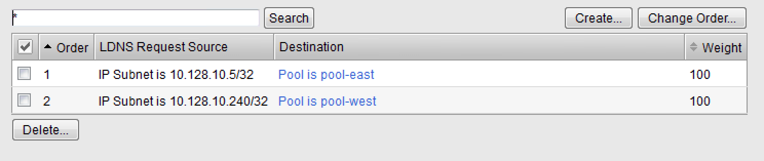
In the GUI, navigate to: DNS > GSLB > Topology > > Records: Create. Create two new records as shown in the tables > below:
Topology Record 1
| Request Source | IP Subnet is 10.128.10.247/32 |
|---|---|
| Destination - Pools – Pool List | pool_west |
| Weight | 100 |
Topology Record 2
| Request Source | IP Subnet is 10.0.0.0/24 |
|---|---|
| Destination - Pools – Pool List | pool_east |
| Weight | 100 |
WideIP
We will create a hostname to use as a Wide IP for Toplogy LB.
- From the GTM1 GUI, navigate to: DNS > GSLB > Wide IPs > > Wide IP List: Create. Create a new Wide IP as shown in the > table below. Keep the defaults if not noted in the table.
| Name | topology.webapp1.com |
|---|---|
| Type | A |
| Load Balancing Method | Topology |
| Pool List | pool_east (add) pool_west (add) |
Issue the following DNS query multiple times from a command prompt on your Windows workstation:
nslookup topology.webapp1.com 10.128.10.245
You should see the IP address for the East Data Center – 10.128.10.10 because you are coming from 10.128.10.5 which falls under Topology Record #1 that you created above.
Open an SSH session to the LTM-east if you don’t have one open already.
IP: 10.128.1.245
User/pass: root/agility
Issue the following DNS query multiple times:
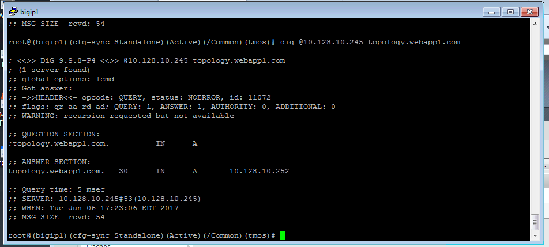
tmsh dig @10.128.10.245 topology.webapp1.com
You should see the IP address for the generic web server in the west data center returned (10.128.10.252).
Synchronization Group
- In this use-case, you will create a sync group to be used between
GTM1 and GTM2
- GTM1 will be used as the “existing GTM”.
- GTM2 will be used as the “new GTM”. This unit will end up consuming and having a copy of the config from the “existing GTM”.
- Estimated completion time: 15 minutes
TASK 1 – Create Server Object on GTM1
- Log in to GTM2 (10.128.1.247) using admin\agility and notice > there is no DNS WideIPs, servers, or data centers configured
- From GTM1 we will need to add GTM2 as a Server object.
- From GTM1 GUI, navigate to: DNS > GSLB > Servers > > Server List: Create
| Name | gtm2-west |
|---|---|
| Product | Big-IP (Single) |
| Address List | 10.128.10.247 (Add) |
| Data Center | West |
| Health Monitors | Bigip |
| Virtual Server Discovery | Disabled |
| Click Create |
Notice the gtm2-west server object stays blue on the server list screen. This is because we haven’t created the trust between the devices yet.
TASK 2 – Create a Synchronization Group
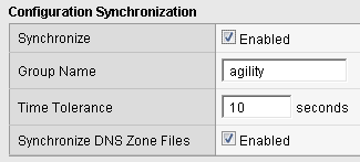
*On GTM1* in the GUI, navigate to: **DNS > Settings > > GSLB > General. **
Enable the Synchronize checkbox.
Change the Group Name as Agility
Enable the Synchronize DNS Zone Files checkbox.
TASK 3 – Add New GTM to Synchronization Group
We will run the gtm_add script to add the “new GTM” to the synchronization group with the “existing GTM”. Note, always run this script on the NEW GTM device. Running this script on the configured GTM device will sync to the new device and erase the current configuration! So be very careful!
Use PUTTY to log in to the new gtm2 (10.128.1.247) with root\agility and run the following command:
gtm_add 10.128.10.241
Type ‘y’ to proceed. If prompted for a password use ‘agility’.
To validate the sync group is setup properly, navigate through the GUI to see if the configurations are the same. You may want to look at the Server definitions, Wide IPs, etc.
If the configs look equal, make a change on one GTM and see if it shows up on the other. Repeat in the reverse direction. **Note - There is NO MASTER! Any change on any GTM in a sync group is automatically replicated to all other GTMs in the group.
From your workstation, query each Listener (gtm1 – 10.128.10.245 and gtm2 – 10.128.10.246) for a given Wide IP and verify that the responses are as expected.